
shared USB switch component selection
I originally wrote most of this post in May 2018 but never posted it because I didn’t like the components I came up with. Recently while looking into it again I found that Texas Instruments had a new IC I’d like to use so I’ll post it now.
This post is all about picking components for the USB switch project. While these could still change, I think they’ll provide a good baseline for what I need.
I’ll go over all the components and discuss which options we have and which I prefer at the moment. Mostly focusing on being able to safely draw power from the input ports.
Charger detection
This component was not discussed in the previous post but is definitely needed to reach our goal.
I want to use the powersource that has the most power available to power all devices. To do this I will need to detect if the input USB ports support charging devices with high current or not. I’d also want to charge actual devices through the device but that might be a bit harder as the USB hub would need to correctly transmit this capability to the upstream device (or it should not advertise it if we don’t have a proper charger connected).
And hopefully I’ll also find a way to not just advertise/not advertise that we are capable of charging a device, but also properly limit the current. In case a device doesn’t follow the specifications and tries to draw more current than allowed, its power should be safely cut off.
The switching IC’s we’d use usually have a version that has the charger detection built in, however those are always designed to operate in the opposite direction of our requirements.
They will detect the charger on 1 input port, and can switch that input to 2 outputs. However we want to separately detect a charger on both of our input ports and then switch one of those to our single output.
So we will need a single chip just for detecting the charger on each input port.
My preferences for this IC are as follows:
- Powered by USB port. I don’t want to use an extra 3.3V or other power supply to power this chip (since each port needs its own IC).
- No BGA. These chips are always very small. I don’t want to make the task of soldering it any worse by choosing a BGA package.
- Simple interface, no SPI or I2C or anything that would require the use of a microcontroller.
I’ve found 3 devices that I think match these requirements and their footprints are near identical that either could be used without modification.
First is the On Semiconductor FSA832, the datasheet on this chip mentions it also supports detecting proprietary chargers but isn’t specific on which ones.
Second is the Maxim MAX14576/MAX14636/MAX14637, these are near identical IC’s with support for different proprietary chargers, with the MAX14636 seeming to support the most.
Third but not least is Texas Instruments BQ24392, this one seems to support all proprietary standards as well and has a more detailed datasheet available.
Either one of these would work in the design with the same footprint, but I prefer the TI one, simply because I liked its documentation the most. It also has an automotive version which is near identical but where they guarantee less broken parts (useful if you’re ordering millions, though they simply guarantee slightly worse nominal specs to reach this lower failure rate).
These IC’s also allow us to detect how much the charger can deliver. Assuming the GOOD_BAT pin is always high (and since we don’t even have a battery, I see no reason why it shouldn’t always be high), we can detect the various states. If the CHG_AL_N pin is low it can only draw 100mA (or 500mA after usb enumeration, though a lot of devices don’t follow this specification and draw 500mA before it is allowed). If the CHG_DET pin is also high it can charge with full current (1.5A) right away without enumeration.
If we also ignore the specs just a tiny bit we can set our current limits to either 500mA or 1.5A.
Power OR-ing
by Texas Instruments Incorporated
Since we now have a way to detect which power source is most suited for our devices, we now need a way to actually switch the power appropriately. This gets a little bit tricky, since we want to select our preferred power source but still automatically (and very quickly) switch to the other one if that power source gets unplugged.
This is the part where I got stuck when I originally started writing the post.
I found a few potential candidates however they would either allow me to manually choose which input I wanted, or switch over to the best powersupply (optionally with a priority over which one to choose if they were both within spec). But they wouldn’t allow me to switch which input line had priority.
Selecting the proper input is further complicated since our detection IC has a delay (could be more than 600ms before it figures things out) and whatever logic we use to select it will need its own power source too.
We could use a separate OR-ing diode pair to power the logic that is independent of the main power switching. The logic ports don’t need exactly 5V(it doesn’t even need to be 5V logic at all really, as long as its inputs can handle 5V for one of the pins of our charger detector), so just regular diodes will do. But this still means more components are needed(the diodes, extra caps).
Since then I’ve found a new part released by TI sometime in December 2018 that would make everything a bit easier.
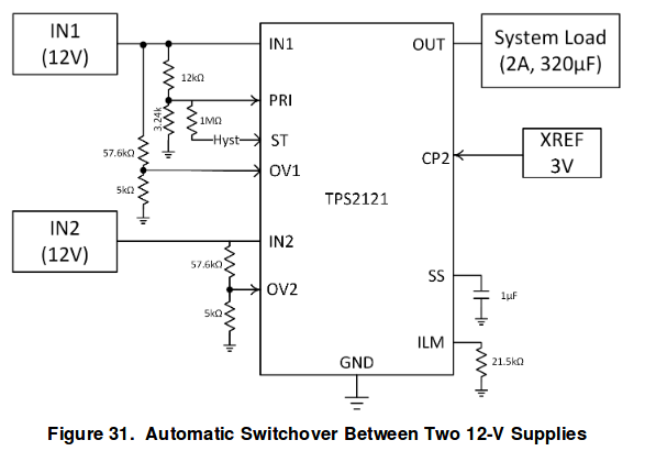
The TPS2121 allows for an operation similar to the previously found parts, but also lets us choose which input source has priority. This operation is used when both power inputs are valid and pin CP2 is high(higher than VREF, typical 1.06V), it’ll then select input 1 or input 2 as priority depending on whether pin PR1 has a higher or a lower voltage than the one on CP2.
| DEVICE INPUTS | DEVICE OUTPUTS | ||||||
|---|---|---|---|---|---|---|---|
| IN1 ≤ UV OR OV1 ≥ VREF | IN2 ≤ UV OR OV2 ≥ VREF | CP2 ≥ VREF | PR1 ≥ VREF | VCOMP | XCOMP | OUT | ST |
| 0 | X | 0 | 0 | IN2 < IN1 | X | IN1 | H |
| X | 0 | 0 | 0 | IN2 ≥ IN1 | X | IN2 | L |
| 0 | X | 0 | 1 | X | X | IN1 | H |
| X | 0 | 1 | 0 | X | X | IN2 | L |
| 0 | X | 1 | 1 | X | PR1 > CP2 | IN1 | H |
| X | 0 | 1 | 1 | X | PR1 ≤ CP2 | IN2 | L |
| 0 | 1 | X | X | X | X | IN1 | H |
| 1 | 0 | X | X | X | X | IN2 | L |
| 1 | 1 | X | X | X | X | Hi-Z | H |
Using this IC I’ll still need some glue logic to select which port has priority and selecting what data input to choose from, but my logic won’t need to be super fast like if I’d have to manually switch input power.
This means no more looking at fast power detection IC’s, no more seeing how cheap small FPGA’s can be, no more seeing if cPLD’s are still available and how to program them. All the logic can be handled by a cheap and slow microcontroller, and if a priority input gets unplugged, the power switching chip will handle it for us.
Unfortunately, this IC doesn’t let us set the under voltage limit (it is fixed somewhere between 2.4V and 2.8V). Which means it’ll still use the priority input even when it goes out of spec for USB (either in auto switch mode, OR in selectable priority mode) and only switch when it goes much lower or is completely unplugged. Perhaps I can come up with a clever way to get it to auto switch when under voltage too by using only some passives. But that is for another post.
USB switch
We previously already found a suitable USB switch by On Semiconductor but now its time to look at the alternatives. I haven’t used much On Semi parts in the past, and I suspect theres a reason for this.
I want a device thats as simple as possible and is preferably easy to solder. Additionally I’d prefer it to be easy to power directly by the USB power line without having to convert it first. Our On Semi part is already near failing at that. It’s max input voltage is 5.6V and its recommended voltage is between 2.4V and 4.4V (which is what we want it to be for it to work reliably). There are plenty of USB chargers that are out of spec and possibly deliver even more. So lets see how the alternatives hold up.
First alternative is the Microchip USB3740. This device comes in a 0.5mm pin pitch UQFM package (or alternatively 0.4mm). Which isn’t very large or easy to solder but it is about the same as our charge detector.
As for input voltage, it can tolerate 6V and the recommended voltage is between 3.0 and 5.5V.
The second and third alternatives are from texas instruments. The TS3USB30E and the TS3USB221 (or one of its variants).
Both of these have a max voltage of 4.6V and a recommended voltage between 2.3 and 3.6. The ts3usb30e comes in 2 packages, a 0.4mm pitch UQFN package or a 0.5mm VSSOP package (easy to solder). The TS3USB221 has variants with a 5mm pitch UQFN package, or 5mm VSON (similar but with a big ground plane under it).
It seems our dream of powering it directly from the 5V line is going to be broken. Though the microchip possibly could probably handle it, I’m not sure I want to risk it. We are still going to need to create 3.3V for our USB hub and maybe microcontroller, so it wouldn’t hurt if we used this here too.
None of our choices are pin compatible so we’ll definitely need to make a choice during the design phase. My current preference is one of the TI chips simply because the TS2USB30E has a version which is easy to solder, and the TS3USB221E has a version with the same footprint as our charger detecting IC (so I don’t need to design a new footprint).
USB hub
The usb hub we picked last time still seems like a good choice. It has support for charging so we can actually charge devices through it. Though the hub itself needs to be reset for charging to be enabled/disabled per port, and I will need to think of a clever way to change the max output current per port depending on our power availability.
Output power
To be safe I need to monitor the output power and ensure we don’t draw too much of it (in addition to short circuit protection). We’ll have to use another IC for this and the real question is if I want to monitor each port individually or not.
I also need to consider how to protect the device when the power input changes. If at some point I have an adapter plugged in, I could draw 1.5A, but if powered by non charge capable devices I’d have to limit the current to 500mA. I can probably reset the hub and have it no longer advertise charging capabilities when I need to limit to 500mA but I also need to measure it and prevent a rogue device from drawing too much.
Both the USB OR-ing chip and any potential power distribution switch sets the current limit with a resistor to ground. We could possibly change the current limit by using 2 resistors in series and pulling their midpoint to ground (in all cases, a higher resistance equals lower allowed current).
So based on what I said above, we can limit the total current by setting a value for the OR-ing power chip and limit the current per port with some other IC.
Total current available (officially) is 1.5A if there is a charger detected. Should I limit each port to 1A and total power to 1.5A? Or 1 port to 1.5A and another to 500mA? Or one to 1A and one to 500mA just to be extra safe?
How much out of spec am I willing to go here? And keeping in mind that the current sensing is not exact and has a large margin of error.
I haven’t decided how to approach this yet. And to make a proper decision I should probably find a way to measure how much current my fancy RGB keyboard draws. But meanwhile I can at least list some of the chips for the finial current sensing/power switching.
Our reference design for the USB hub we’re using uses a MIC2026A for its power switching. It’s a single chip that has 2 power outputs of 500mA each (no programmable current limit).
A newer alternative would be something like the MIC2019. It is only a single port but can be set to 2A. Or maybe an UCS2113 which has 2 ports of up to 3A each.
Logic
To decide which port to draw power from, we’re going to need some fast logic. If I can’t do this in a clean way with just some passives, I will drop that requirement and have 1 primary charging input instead of switching between 2 chargers.
To decide which port to switch to for our data we also need some logic, though that doesn’t need to be as fast and a microcontroller would be nice for this so we can use it to optionally reset the USB hub.
I’m definitely not planning on mass producing this first version so the micro I choose will be something I like and can easily program, not necessarily the cheapest one for the job. After all this is more of a proof of concept, afterwards I can think about USB3 support, USB-PD over USB-C port, more inputs, more outputs, etc.